The dipole antenna or dipole aerial is one of the most important and commonly used types of RF antenna.
The dipole aerial or antenna is widely used on its own, but it is also incorporated into many other RF antenna designs where it forms the radiating or driven element for the overall antenna.
The dipole is a simple antenna to construct and use, and many of the calculations are quite straightforward. However like all other antennas, the in-depth calculations are considerably more complicated.
Dipole antenna basics
As the name suggests the dipole antenna consists of two terminals or “poles” into which radio frequency current flows. This current and the associated voltage causes and electromagnetic or radio signal to be radiated.

Basic dipole antenna
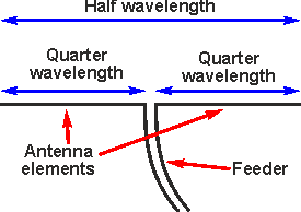
As seen the antenna consists of a radiating element that is split, normally in the centre to allow a feeder to apply power to it from a transmitter, or to take power from it to a receiver.
The length of the radiating element determines many of the properties of the dipole antenna from its impedance, centre operating frequency, etc. As such this is an important feature of the antenna.
Often the term dipole antenna tends to indicate a half wave dipole. This is by far the most widely used length for a dipole. It forms a resonant circuit which resonates where the electrical length is half a wavelength long – the electrical length differs from the wavelength of the signal in free space because of a number of the effects of the radiating element on the signal and it is very slightly shorter than the signal e/m wavelength in free space..

Half wave dipole antenna
Although the half wavelength dipole antenna is the most popular, a variety of other formats are also available.
Dipole types
The dipole antenna consists of two conductive elements such as metal wires or rods which are fed by a signal source or feed energy that has been picked up to a receiver. The energy may be transferred to and from the dipole antenna either directly straight into a from the electronic instrument, or it may be transferred some distance using a feeder. This leaves considerable room for a variety of different antenna formats.
Although the dipole antenna is often though in its half wave format, there are nevertheless many forms of the antenna that can be used.
- Half wave dipole antenna: The half wave dipole antenna is the one that is most widely used . Being half a wavelength long it is a resonant antenna. Read more about the Half wave dipole
- Multiple half waves dipole antenna: It is possible to utilise a dipole antenna or aerial that is an odd multiple of half wavelengths long.
- Folded dipole antenna: As the name implies this form of the dipole aerial or dipole antenna is folded back on itself. While still retaining the length between the ends of half a wavelength, an additional length of conductor effectively connects the two ends together. Read more about the Folded-dipole
- Short dipole: A short dipole antenna is one where the length is much shorter than that of half a wavelength. Where a dipole antenna is shorter than half a wavelength, the feed impedance starts to rise and its response is less dependent upon frequency changes. Its length also becomes smaller and this has many advantages. It is found that the current profile of the antenna approximately a triangular distribution. Read more about the Short-dipole
- Non-resonant dipole: A dipole antenna may be operated away from its resonant frequency and fed with a high impedance feeder. This enables it to operate over a much wider bandwidth.
Dipole antenna current & voltage distribution
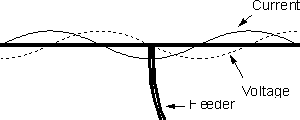
The current and voltage on a radiating element vary along the length of the dipole. This occurs because standing waves are set up along the length of the radiating element and as a result peaks and troughs are found along the length.
The current falls to zero at the end and rises towards the middle. Conversely, the voltage peaks at the end and falls as the distance from the end increases.
Both the current and voltage on the dipole antenna vary in a sinusoidal manner, meaning that there may be other peaks and troughs along the length of the radiating sections dependent upon their length.
The most popular form of dipole antenna is the half wave and for this, the current is at a minimum at the ends and rises to a maximum in the middle where the feed is applied. Conversely the voltage is low at the middle and rises to a maximum at the ends. It is generally fed at the centre, at the point where the current is at a maximum and the voltage a minimum. This provides a low impedance feed point which is convenient to handle. High voltage feed points are far less convenient and more difficult to use.
When multiple half wavelength dipoles are used, they are similarly normally fed in the centre. Here again the voltage is at a minimum and the current at a maximum. Theoretically any of the current maximum nodes could be used.

Three half wavelength wave dipole antenna
The dipole antenna is a particularly important form of RF antenna which is very widely used for radio transmitting and receiving applications. The dipole is often used on its own as an RF antenna, but it also forms the essential element in many other types of RF antenna. As such it is the possibly the most important form of RF antenna.
By Ian Poole
Views: 52

